Overview
Semester-long engineering project replacing Professor Harris's 28-year-old failing demonstration board for E85 (Digital Electronics and Computer Engineering). Designed modular board with 7 logic gates, push-button inputs, high-visibility LEDs, and 555 timer clock. Used laser-cut plywood and 3D-printed color-coded gate inlays for durability and visibility.
Delivered board designed to last 30+ years, visible across 50-foot lecture halls, and came in under budget at $71.05 (vs $150 budget). Restored interactive hardware demonstrations for approximately 40 students per semester in Harvey Mudd's core Digital Electronics and Computer Engineering course.
Design & Development
Impact
Built to outlast the original 28-year board
Under budget ($150 allocated)
High-visibility LEDs across lecture hall
Restored interactive demos for E85 course
The Problem
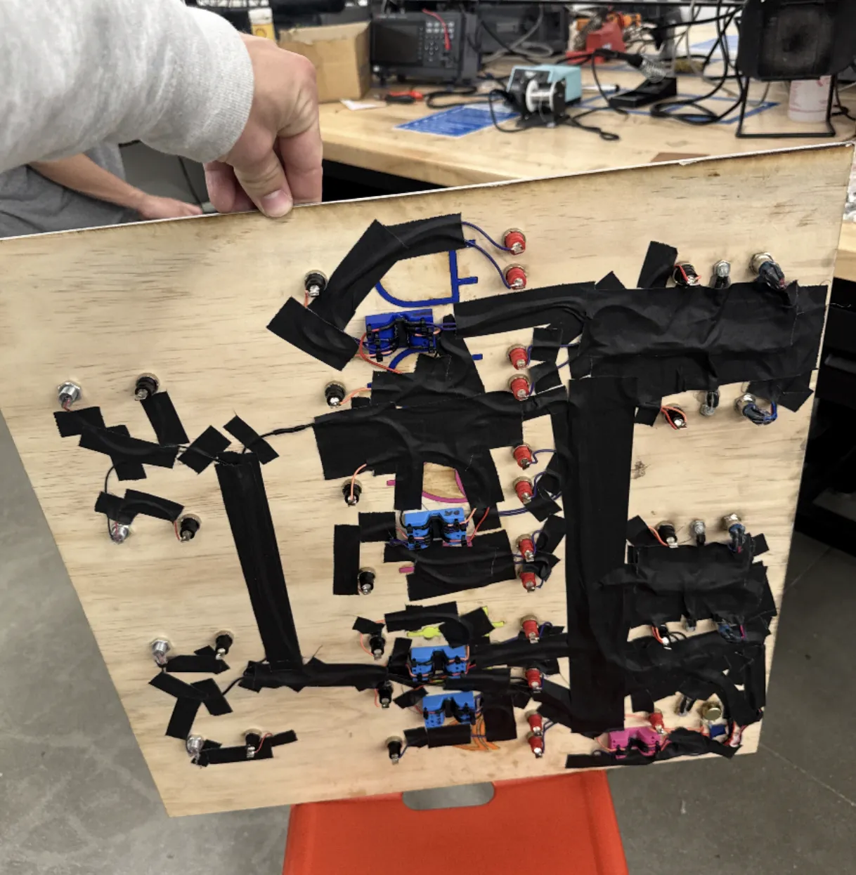
Professor Harris's original logic gate demonstration board had served Harvey Mudd's Digital Electronics and Computer Engineering (E85) course for 28 years, but was failing after decades of classroom use. The board was essential for demonstrating fundamental logic gate operations—AND, OR, NOT, NAND, NOR, XOR, and XNOR—to students learning digital circuit design.
Without a working demonstration board, students lost valuable hands-on visual reinforcement of abstract concepts. The challenge: design a replacement board that would be durable enough to last another 30+ years, visible across large lecture halls, modular for easy maintenance, and achievable within a $150 budget.
Design Solution
Modular Architecture
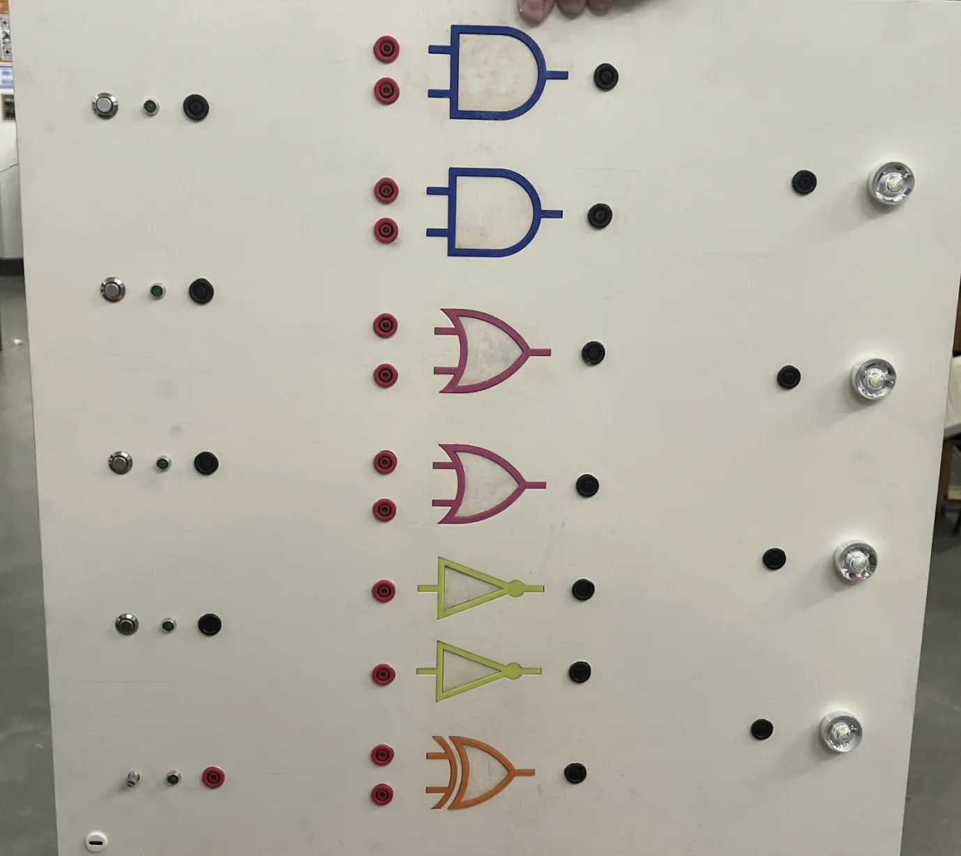
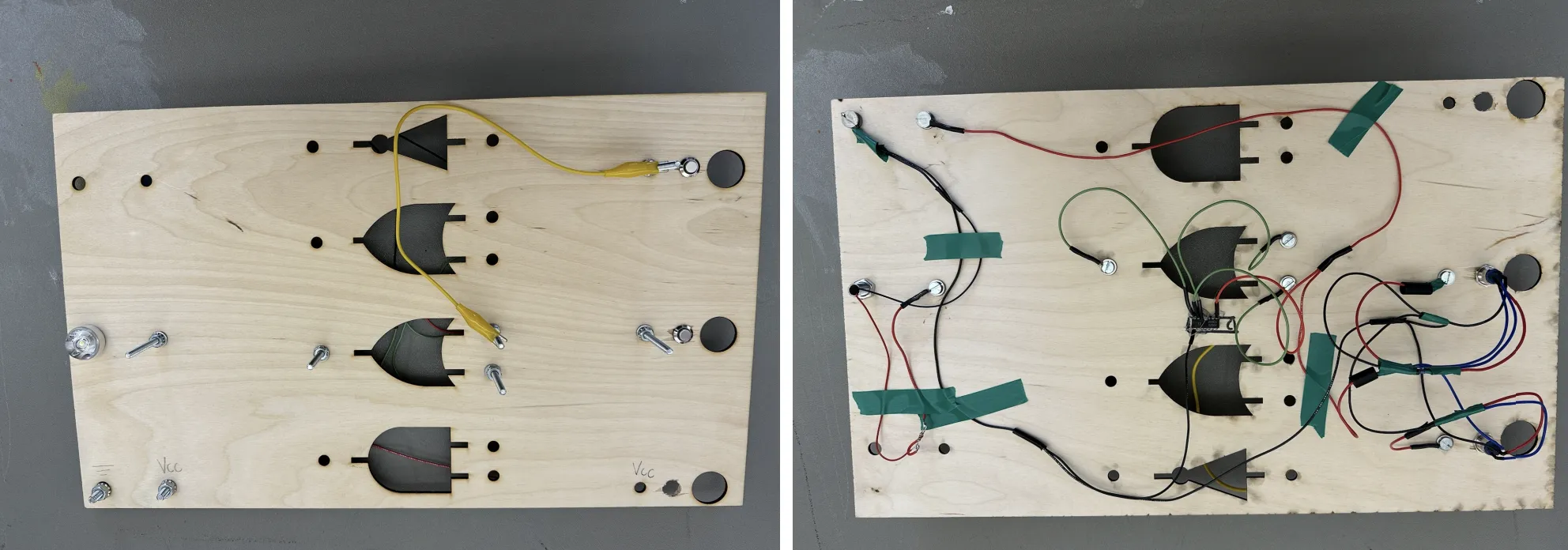
Designed board with 7 independent logic gate modules (AND, OR, NOT, NAND, NOR, XOR, XNOR), allowing individual gates to be serviced or replaced without rebuilding the entire system.
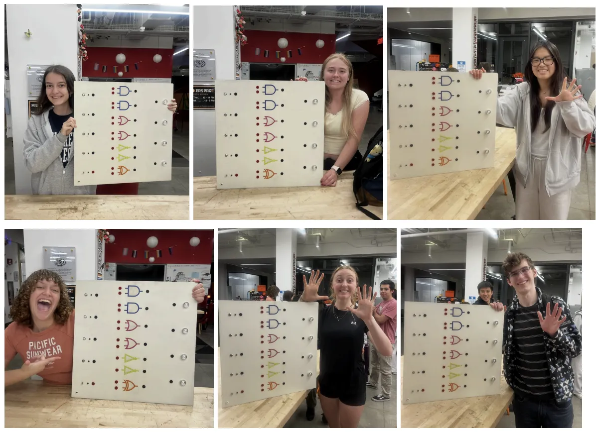
High-Visibility LEDs
Implemented bright LEDs visible from 50 feet away, ensuring all students in large lecture halls can clearly see gate outputs during demonstrations. Color-coded indicators make logic states immediately apparent.
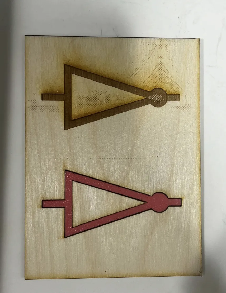
Durable Materials
Laser-cut plywood base provides structural rigidity while 3D-printed color-coded gate inlays offer visual clarity and protect circuitry. Materials selected for longevity and ease of replacement if needed.
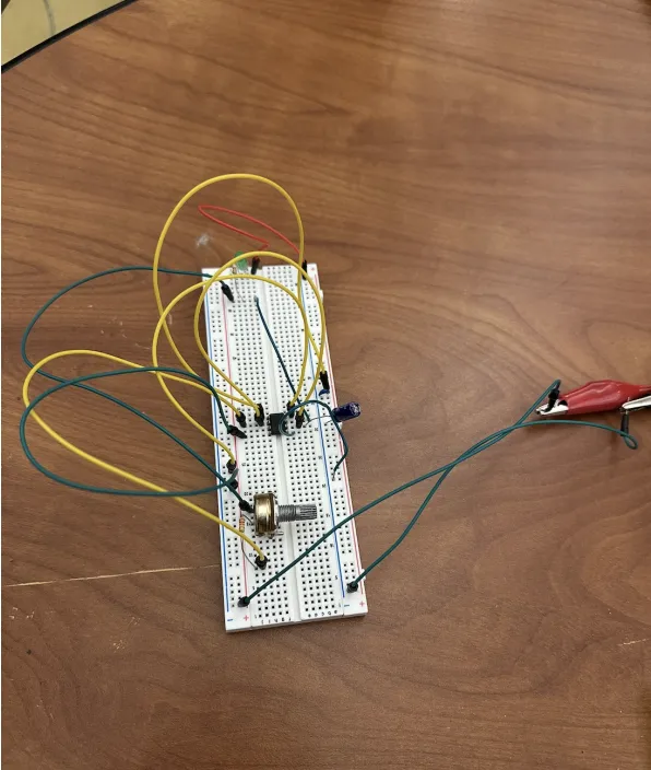
555 Timer Clock
Integrated NE555 timer provides adjustable clock signal for demonstrating sequential logic and timing concepts, adding versatility beyond simple combinational logic demonstrations.
Technical Implementation
The board uses 74HC series CMOS logic ICs for low power consumption and high noise immunity. Each gate has dedicated push-button inputs and LED outputs, allowing Professor Harris to demonstrate truth tables and Boolean algebra concepts interactively.
Key Technical Specifications:
- Logic Gates: 7 fundamental gates (AND, OR, NOT, NAND, NOR, XOR, XNOR) using 74HC series ICs
- Clock Generator: NE555 timer with adjustable frequency for timing demonstrations
- Input Interface: Push-button switches with debouncing for reliable operation
- Output Display: High-brightness LEDs visible from 50+ feet
- Manufacturing: Full Spectrum laser cutter for plywood base, Bambu Lab X1-Carbon for 3D-printed components
- Design Tools: SolidWorks CAD for mechanical design and layout optimization
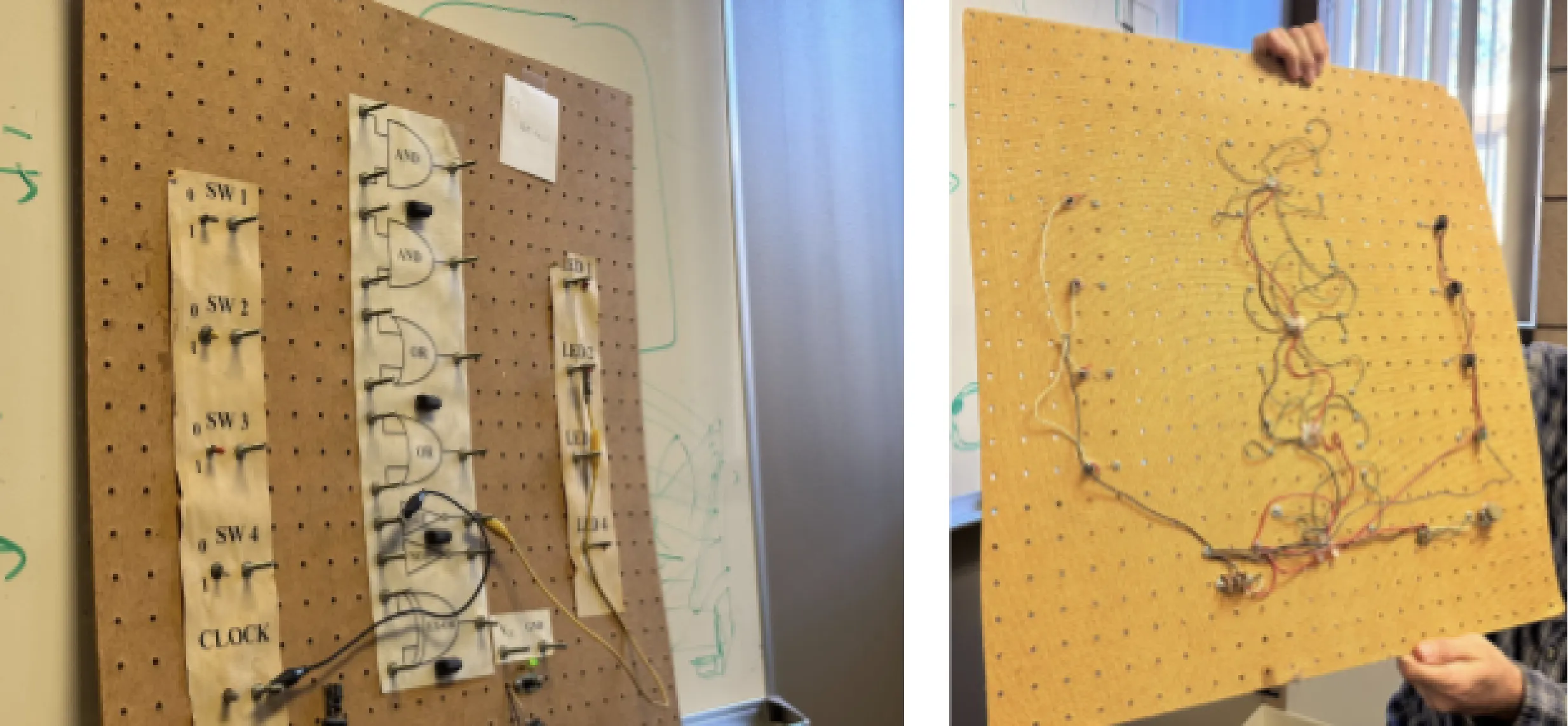
Design Process
The project followed a structured engineering design process including stakeholder interviews, requirements analysis, iterative prototyping, and user testing. Key design decisions prioritized durability, visibility, and maintainability.
Design Iterations:
- Conducted interviews with Professor Harris to understand pain points with original board and teaching requirements
- Created multiple layout concepts balancing size, visibility, and manufacturing constraints
- Prototyped individual gate modules to test LED brightness, switch reliability, and mounting approaches
- Gathered feedback from target users (students and professor) to refine design before final fabrication
- Optimized component selection to stay under $150 budget while maximizing quality and longevity
Budget & Cost Management
Delivered final board for $71.05, coming in 53% under the $150 budget. Cost savings achieved through strategic material selection, efficient laser cutting layouts to minimize waste, and leveraging Harvey Mudd's existing fabrication resources (laser cutter and 3D printer access).
This under-budget delivery demonstrates engineering value optimization—achieving design goals while minimizing resource consumption. Remaining budget provides cushion for future repairs or enhancements if needed over the board's 30+ year lifespan.
Tags
Board Demonstration
Watch a demonstration of the Logic Gate Demo board showing all seven logic gates in operation, push-button inputs, LED outputs, and the 555 timer clock functionality.